RF Capacitance vs. Guided Wave Radar Technology
RF Capacitance Technology
The liquid acts as an isolator between two conductors (probe and tank wall). When level rises, there is more gain of capacity into an analog or digital signal. The technology requires the use of a rod or cable probe to be immersed in the liquid level to be measured.
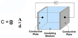
RF capacitance electronic level measurement utilizes the same fundamentals as any electronic capacitor. A capacitor is formed when an AC signal is applied across two conductive plates separated by an insulating medium, or dielectric. The value of a capacitor is determined by the: (see fig. 1.0)
- area of the conductive plates (A)
- distance between the plates (D)
- dielectric of the insulating medium between the plates (E)
Capacitance = E*A/D (The AC frequency is fixed as part of the design.)
Capacitance is measured in Farads and the value we utilize in industrial measurement is an extremely small unit called a pico Farad (pF). A pico Farad is one trillionth of a Farad.
The capacitance value increases as the dielectric increases, the plate size increases, or the distance between the plates decreases.
In industrial applications, the probe is one plate of the capacitor, the tank wall is the other plate (ground reference). The insulating material that separates them is the dielectric. A tank that is empty is actually filled with air that has a dielectric of 1, the baseline of the dielectric scale. All materials have a dielectric higher than air, e.g. oil = 2.5, alcohol = 18, tap water = 80, etc. As a tank is filled with  media, the air (dielectric 1) is being displaced by the media having a higher dielectric; consequently, the amount of capacitance being generated between the probe and the tank wall increases. This capacitance change, corresponding to the rising or falling of media in a tank, can be detected by either a point level device yielding a contact closure; or, a transmitter yielding a continuous output.
Fig. 1.0
Conclusion: RF Capacitance level measurements require the liquid to be measured to be consistent in dielectric properties and specific gravity. If the electrical properties of the fluid being measured will vary, the calibrated output will also vary. If the probe of the sensor is coated with material that differs in electrical properties of the fluid being measured, likewise the calibrated output will also vary.
GWR Technology
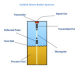
High frequency electromagnetic pulses are transmitted along a stainless steel rod probe or cable probe that is immersed in the liquid or dry solid or the material to be measured. The-high frequency electromagnetic pulses transmitted down the probe are reflected at the point of discontinuity between the air and the process medium. As with other “time of flight” instruments, those reflections are measured by high-speed circuitry in the transmitter, thus establishing the level measurement.
Time taken by the pulses to go down and reflect back is determined to measure level of the fluid.
In this method, the degradation of the signal in use is very less since the waveguide offers extremely efficient course for signal travel. Hence, level measurement in case of materials having very low dielectric constant can be done effectively. Also in this invasive measurement method, pulses are directed via a guide; hence factors like surface turbulence, foams, vapors or tank obstructions do not influence the measurement.
GWR method is capable of working with different specific gravities and material coatings. However, there is always a danger that the probe or rod used as a waveguide may get impaired by the agitator blade or corrosiveness of the fluid under measurement. A typical guided wave radar system is shown in the figure below. The dielectric constant for typical process media can range from 1.0 –100.0 without affecting the calibrated output or accuracy of measurement. see fig. 1.1

GWR technology is also unaffected by varying temperature and pressure changes in the vessel to be measured.
Conclusion: GWR technology gives a very precise continuous reading, is energy efficient (a consideration for potential battery-powered wireless connectivity), and can operate in difficult situations where other approaches fail.
The probe concentrates the energy pulse much as speaking through a tube concentrates the sound. This is particularly useful under certain conditions where a through-air pulse is less reliable:
- Emulsion buildup on the probe has no affect on accuracy;
- Liquids that have low dielectric values (e.g., propane, butane);
- Interface level measurements;
- Low specific gravity liquids;
- Uneven sureface conditions even in dry powder applications;
- Turbulent liquids;
- Air space with condensing humidity
- Internal physical obstructions (e.g., baffles);
- full vacuum, high pressure and temperature variations have no affect on accuracy;
- Lower cost than Through-The-Air Radar Transmitters;
- Heavy foam layers; and,
- Problematic solids.
View our U.S. Manufactured TDR, the Tracer 1000™ 3G GWR Level Transmitter


